


 Back to Blog
By Lauren Nagel
The electronic speed controller (ESC) is an essential part of an electric propulsion system’s hardware. It acts like the brain of the system by telling the motor how fast to go based on data signals it receives from the throttle controller.
For smaller applications like drones and RC vehicles, this controller has the name ‘ESC’, whereas for larger manufacturing applications it may be called an electronic control unit, inverter, or motor controller.

Figure 1: Afro Race Spec 20A ESC
The mechanism within the ESC as well as its interaction with the battery and motor are quite fascinating. In this article we will cover the fundamentals on how ESCs work, the protocols they use, and how they are used to control brushless motors and drones.
Table of Contents
- How Does an ESC Work
- ESC Components: Microcontroller (MCU), Gate Driver, MOSFETs, Battery Eliminator Circuit (BEC), Device Manager Adapter (DMA)
- What is PWM
- ESC Protocols
- ESC for Brushless Motors
- ESC for Drones + How to Choose an ESC
How Does an ESC Work
The role of the ESC is to act as the regulating middleman between the battery and the electric motor. It controls the rotation of the motor by delivering timed electric signals that are translated into changes in speed. It uses the direct current from the battery coupled with a switch system to achieve an alternating three-phase current that is sent to the motor.
The vehicle’s throttle controller is used to vary the speed of the motor, whether it be an electric car, plane or drone. Increasing the throttle increases the output power, which modifies the rate at which the switches open and close in the ESC’s circuit.

Figure 2: The controller communicates with the drone’s onboard throttle receiver
There are several signal delivery protocols that are used to convey throttle information from the remote controller to the ESC. Each protocol has a slightly different performance, the most common ones being PWM, Oneshot, Multishot and Dshot.
The most important difference between them is the frequency of the signals they deliver. Shorter frequencies allow a faster signal and a quicker drone reaction time. Furthermore, the Dshot protocol is different from the others because it sends a digital signal instead of an analog signal. This makes the signal more reliable since it is less sensitive to electrical noise and is more precise with its higher resolution. We will cover this in more detail later in this article.
Browse ESC test performance with our ESC Performance Database
ESC Components
Within the ESC there are a number of important components, including the microcontroller, gate driver and MOSFETs (figure 3), as well as the battery eliminator circuit and device manager adapter in some cases.

Figure 3: The key components of an ESC
Microcontroller (MCU)
The microcontroller plays three key roles in the ESC’s operation: 1) housing the firmware that interprets the signal from the controller and feeds it in a control loop, 2) keeping track of the motor’s position in order to ensure smooth acceleration, 3) sending pulses to the gate driver to achieve the desired command
The firmware used in ESCs is often pre-installed by the manufacturer, but open source versions can also be obtained from 3rd party sources. In hobby drones, the pre-installed firmware is generally a variation of BLHeli (either BLHeli_S or BLHeli_32), though other softwares like SimonK and KISS are also available. The chosen firmware must be compatible with the hardware as it will determine the ESCs performance and what protocols can be used.
The microcontroller also determines the motor’s position through a sensored or sensorless system. Sensored systems use electronic sensors in the motor to track the rotor’s position, which is great for low speed, high torque applications such as ground vehicles. The more popular sensorless systems use back EMF to determine the location of the rotor relative to the stator. This works great at high speeds, though when the motor is turning at lower speeds with less back EMF, the sensorless system does not work as well. This is generally not an issue when driving a propeller. Overall, for high speed applications, the sensorless system is more efficient, cheaper and more reliable.
Gate driver
The gate driver’s job is to act as the middleman between the controller and the gate of the MOSFETs. Upon receiving a low-voltage signal from the microcontroller, the gate driver amplifies the signal and delivers a high-voltage signal to the MOSFETs. The driver has lower resistance than the microcontroller so can deliver higher current, which also amplifies the speed of the signal. This allows for faster switching and lower heat production. Some ESCs have insulation optical chips between the low voltage microcontroller and the high voltage transistors. Manufacturers may call those ESCs Opto-ESCs.
MOSFET
The Metal Oxide Semiconductor Field Effect Transistors or MOSFETs are the switches that strategically deliver power to the motor. The ESC has six of these transistors and each wire from the motor is connected to two of them. The MOSFETs receive signals from the microcontroller then deliver power to the motor so that each of its coils is in one of three phases: high voltage, low voltage, or off/ grounded
As the motor rotates, the signals from the MOSFETs switch the phases of the coils so the rotor keeps spinning. The ESC uses direct current coupled with the switch system to achieve an alternate three-phase current (figure 4). The higher the throttle input, the faster the switching frequency, leading to a higher RPM in the motor. There are several signal delivery protocols that control this process, each with a different performance and signal frequency.

Figure 4: Opening and closing of switches in an ESC circuit
Battery Eliminator Circuit
ESCs often have a built-in battery eliminator circuit (BEC), which doesn't eliminate the need for a battery, but acts as a voltage regulator to eliminate the need for a separate battery for on-board electronics. The power going through the BEC is dropped to a lower voltage, usually 5 V, which safely powers the throttle receiver and any other devices on board (figure 5).

Figure 5: Electric propulsion system wiring including an ESC and BEC
Device Manager Adapter (DMA)
The device manager adapter (DMA) allows the user to connect their ESC to their computer to download firmware updates and use advanced programming options to customize their device. This keeps the ESC up to date and allows for control of advanced settings such as voltage cut-off, throttle calibration mode, and motor direction.
This component is generally brand-specific and is not available for all ESCs.

Figure 6: DMA from KDE Direct compatible with their UAS ESCs
What is PWM
Pulse width modulation (PWM) was the first ESC protocol and it is still used to this day. PWM uses timed power pulses to tell the motor how fast to turn, based on input from the throttle controller. The throttle controller sends a signal to the ESC’s microcontroller which tells it how much voltage to draw from the battery and deliver to the rotor.
The signal is delivered as pulses, whose width determines for how long voltage is drawn. Voltage pulses (‘on’) are separated by ‘off’ periods where no voltage is delivered. The greater the ratio of ‘on’ time to ‘off’ time, the more power is delivered and the faster the rotor will turn. The ratio of ‘on’ to ‘off’ time is also called the duty cycle.
In a PWM system, the length of the pulses varies from ~1000μs to ~2000μs.Originally, pulses were sent every 50ms, but this has increased over time so the signal is sent every 2.04 ms (490Hz). If the frequency were 500 Hz, the signal could potentially be 100% ‘on’, which would be detected as a fault.
The gate driver takes the voltage from the microcontroller and delivers it to the MOSFETs, where it drives them to switch between its three phases. The more voltage arriving at the MOSFETs, the faster they switch phases, and the faster the rotor turns.
If you plot time on the x-axis and voltage on the y-axis, you can see how ‘pulse width’ is controlled or modulated in this system (figure 7).

Figure 7: Pulse length in ms at min and max throttle
You can estimate your RPM by taking the average voltage over time (for both ‘on’ and ‘off’ signals) and multiplying that by your motor’s Kv rating.
ESC Protocols
The ESC protocol is essentially the language that the flight controllers use to communicate with the ESC. They use unique signal patterns as a way of conveying throttle information while varying the speed of the signal to vary the motor’s rotation speed.
Common ESC Protocols
Prior to 2015, PWM was the only ESC protocol commercially used by small UAVs. Since then, several new protocols have been created and it is common for hardware developed after 2017 to support all or most of them.
The most commonly used protocols include Oneshot125, Oneshot42, Multishot, and Dshot300, Dshot600 and Dshot1200. The Oneshot and Multishot protocols use analog signals like PWM, whereas Dshot (Digital shot) uses a digital signal.
Analog protocols require calibration to ensure that the oscillators (clocks) in the flight controller and ESC are synced, while digital protocols do not require this step. Without this calibration, your drone might not respond as expected due to the ESC misinterpreting the length of signals.
DShot
Dshot1200 is the fastest protocol, delivering 1,200,000 bits of data per second. Dshot1200 has a fixed signal length of just 13 μs, which is almost twice as fast as Multishot, the next fastest protocol, with a 25 μs signal length (figure 8). While Dshot1200 is impressively fast, some say the difference between Dshot600 and Dshot1200 is negligible in practice.

Figure 8: Signal length for common protocols in microseconds
A lower latency means a faster reaction from the vehicle, but there are diminishing returns, especially for larger airframes, due to the inertia of the quadcopter and the propellers. An aggressive flight controller also consumes significantly more power, so it is not advisable to use one if the vehicle does not require it.
Proshot
Proshot is a unique protocol that contains elements of both digital and analog signals. This protocol encodes a DShot signal into PWM pulses - each pulse containing 4 bits of data. This encoding means that you can fit 16-bits of data into just 4 PWM pulses. Similar to DShot, ESC calibration is not required when using Proshot.
Proshot1000 delivers 1,000,000 bits of data per second, slightly less than the fastest DShot protocol. There is debate as to which protocol has higher CPU usage in practice, with no across-the-board answer yet.
Since 2018, there have been ESCs on the market that can support Proshot through BLHeli_32 firmware.
ESC for Brushless Motors
As we’ve learned, the role of the ESC is to deliver power from the battery to the motor in a controlled manner. If you input 50% throttle on the controller, the ESC will deliver 50% ‘power’ to the motor. What is ‘power’ depends on the firmware used. Some will use the average voltage sent to the motor, others use the speed target, and some use a mix of both.
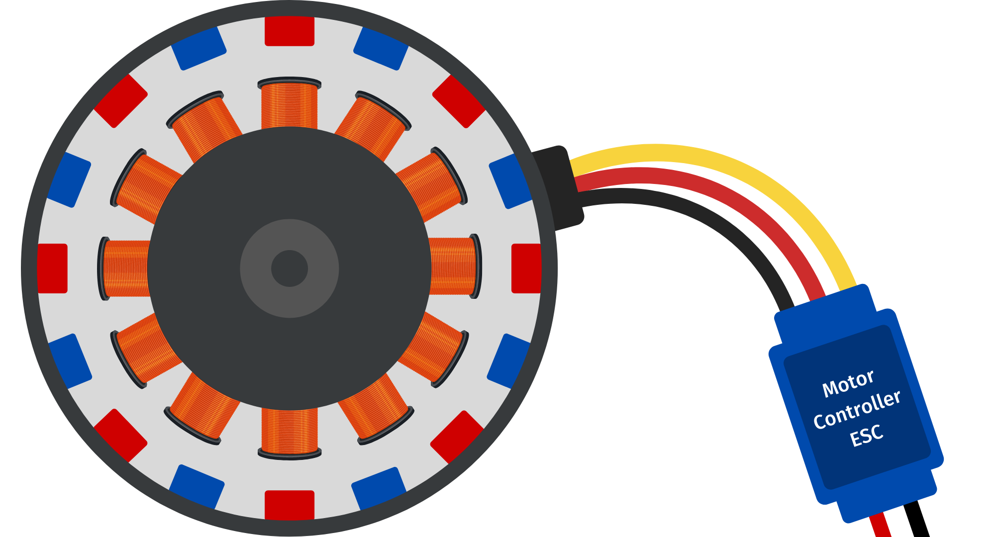
On one end, the ESC has two wires to connect to the battery, a red (positive) wire and a black (negative) wire (figure 9). On the other end are three wires that connect the ESC to the brushless motor. If the motor spins in the wrong direction after connecting it to the ESC, switching any two of the wires will make it spin in the right direction. The final extension connects to the throttle receiver, which is powered by the BEC.

Figure 9: ESC with wiring for the battery (left), throttle receiver (middle) and motor connections (right)
Within the brushless motor are two components: the rotor (containing permanent magnets) and the stator (containing copper coils). When a current is delivered to a coil of the stator, it becomes an electromagnet and develops a North and South pole. When the polarity of the electromagnet matches that of the permanent magnet it faces, their like poles repel and the rotor spins. The current is delivered by the ESC as a three-phase signal that constantly changes the polarity of the electromagnets, that way the rotor keeps spinning.
In order to start this process, the ESC needs to know the position of the rotor to be able to choose which electromagnets to activate. To determine its position in sensored motors, the ESC uses Hall Effect sensors.This information is used to precisely synchronize the phase output with the angle of the rotor in order to ensure a smooth acceleration. In motors without sensors, more commonly used on UAVs, the start process is a bit less robust. The ESC will send a predetermined sequence to the motor to make it start. As soon as the motor has enough speed, the back electromagnetic force (back EMF) will be sufficient for the ESC to obtain a precise position estimate and synchronize the pulses.
For more information, check out our article on How Brushless Motors Work
ESC for Drones + How to Choose an ESC
Choosing an ESC is an important part of the drone design process. You want to ensure that it meets the electrical needs of your aircraft without draining your battery more than necessary. Below are a few factors to consider when choosing an ESC.
ESC Current Rating
The ESC's current rating should be 10 - 20% higher than the motor’s. This will prevent it from overheating and provide a bit of wiggle room when operating at max throttle. You do not want to go much higher than this range to minimize weight. The ESC should be tested in conditions similar to flight as the main limitation is thermal. High temperature and low air circulation will reduce the ESC rating and operating life. Some ESCs have two current ratings: continuous and burst. The continuous current is sustainable for prolonged periods of time and the burst current for short periods only.
ESC Voltage
ESCs have a maximum voltage limit that may be given as a voltage range or a cell range. For example, an ESC rated for 3S - 8S cells will support a voltage of 11.1 - 33.6 V. The ESC may let you set a switch-off voltage that will alert you when the battery voltage becomes too low (3.0 - 3.4 V per cell) to avoid damaging the battery. Those systems are called Low Voltage Cut Off (LVC) and they will reduce the maximum power that the ESC can provide. Eventually, the ESC will shut down the motor.
4-in-1 ESC for Quadcopters
When wiring ESCs into a quadcopter you can have one ESC for each motor or use a 4-in-1 ESC with a single board and four motor connectors (figure 10). Having four ECSs can help spread the heat load if the motors have a high power draw while a 4-in-1 ESC is a great option for saving space and limiting weight from hardware.

Figure 10: 4-in-1 ESC from iFlight
Conclusion
In this article we’ve covered the ESC basics: how they work, the key components, the protocols, and how they work with brushless motors and drones. Having a good understanding of this essential drone component can help you improve your knowledge and your build.
For more information on optimizing your drone, check out our free eBook on Drone Building and Optimization.
If you have any questions, don’t hesitate to leave us a comment below.


FOURDAN Louis
March 22, 2024
Hello Lauren
Is there any ESC included in the 1585 bundle ? or optional / extra ?
If the user installs his favourite 60A ESC, using a standard “servo cable” …
what happens is the user ESC is with SBEC ?
Louis