
 Back to Blog
By Michele Lorusso and Soudeh Tavousi
Electromagnetic interference (EMI) is a common and often frustrating challenge when testing drone propulsion systems. Symptoms linked to EMI can lead to test interruptions, especially in high power test setups where motors, ESCs, and measurement electronics are operating simultaneously.
In practice, EMI can be difficult to trace to a single source. Based on our experience with multiple customer test systems, EMI related issues are often resolved through careful layout, wiring, and grounding practices. In cases where passive measures are not sufficient, active mitigation techniques can be used to further isolate sensitive electronics.
This article outlines common sources of EMI in drone testing and practical methods to reduce it.

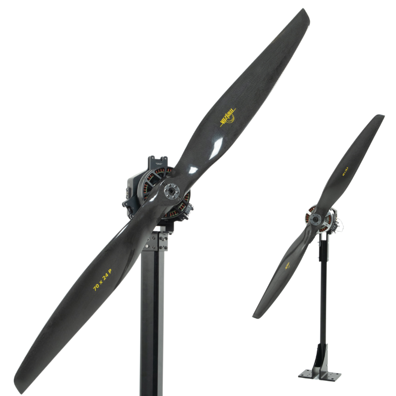
Figure 1: Drone propulsion testing setup with the Flight Stand 15
Table of Contents
- Sources of EMI in drone testing
- Propulsion system components
- Test equipment
- Test environment
- How to reduce EMI
- How to measure EMI
- EMI reduction workflow
- Passive EMI reduction techniques:
- Wiring adjustments
- Ground loops and grounding
- Mechanical EMI sources and isolation
- Ferrite beads and EMI filters
- Connections
- Active EMI reduction techniques:
- Isolating the grounds
- Example: optocoupler
1. Sources of EMI in Drone Testing
EMI often manifests as intermittent disconnects rather than consistent failures, making it difficult to identify the root cause.
EMI can originate from both mechanical and electrical sources. Mechanical sources include sparking or intermittent contact from components such as ignition starters or relays, while electrical sources include high speed switching electronics, power converters, and digital control signals. Understanding the nature of the source helps guide where to focus mitigation efforts.
Below are some of the common sources of EMI in drone testing.
Propulsion system components
In drone testing environments, EMI is primarily generated by components that draw high power or switch rapidly. Motors and ESCs are major contributors, particularly due to high current transients and PWM switching. High voltage battery lines can also radiate noise, and long cable runs can act as antennas.

Figure 2: Drone propulsion system mounted on the Flight Stand 50
When you purchase a new component for your propulsion testing setup, ensure that you read the user manual carefully and look for specific instructions regarding EMI reduction. We have encountered certain models of ESCs and cooling pumps that seem to add extra EMI to a system, and the component manufacturers often have additional EMI mitigation steps in their manuals and datasheets, so check these documents for tips.
Test equipment
Test equipment such as measurement units and external power supplies further complexify the system. These components introduce more wiring, additional grounding paths, and more opportunities for noise to couple into sensitive electronics.
Bellow is a diagram of a correctly arranged drone testing setup with a Flight Stand test stand, motor, ESC, battery, Electrical Measurement Unit (EMU), Sync Hub:

Figure 3: A correctly configured propulsion testing setup
In addition to connecting the system components in this way, we recommend connecting devices directly to the computer when possible and avoiding the use of USB hubs.
Test environment
Environmental conditions can influence EMI behaviour in subtle but meaningful ways.
Temperature affects semiconductor switching behaviour, with hotter devices typically switching slightly slower and colder devices producing sharper edges that increase high frequency emissions, while oscillators and clocks may drift with temperature.
Humidity primarily affects surface conductivity and coupling rather than emissions directly. Low humidity increases static charge buildup and ESD risk, while high humidity can increase surface leakage on cables and PCBs and slightly dampen radiated fields.
Temperature and humidity together alter the dielectric properties of air, which can slightly affect electromagnetic propagation and antenna coupling.
Although these effects are usually small and often below 1 to 3 dB, they can contribute to variability that causes EMI issues to appear as intermittent disconnects rather than repeatable failures.
2. How to Reduce EMI
How to measure EMI
EMI in a propulsion testing setup is commonly evaluated using near field measurements and frequency domain analysis to identify emission sources and coupling paths.
Recommended equipment for initial EMI evaluation includes: an oscilloscope to check for ground loops, and a spectrum analyzer for more detailed frequency analysis.

Figure 4: An oscilloscope (left) and a spectrum analyzer (right)
For more advanced EMI analysis, our team at Tyto has also employed additional equipment including a magnetic near field probe, an inline low noise preamplifier, a fixed attenuator for input protection and linearity, and an oscilloscope with a differential probe to correlate spectral emissions with switching behaviour on power and signal lines. For basic troubleshooting, this additional equipment is unnecessary.

Figure 5: A high voltage differential probe, useful in some cases but unnecessary for basic EMI troubleshooting
To establish the instrument floor, power off all equipment and perform a near field scan using a fixed geometry with the magnetic field probe held at a consistent distance from the chassis, a fixed impedance path, fixed bandwidth settings, and a fixed preamplifier configuration, then treat the resulting baseline level as the local noise floor for comparison.
Use the magnetic near field probe to scan motors, ESCs, cables, and chassis surfaces. Emissions are observed across a wide frequency range and interpreted relative to the local noise floor, with elevated frequency bins (anything ~20 dB over floor) flagged for further investigation and mitigation.
EMI reduction workflow
When EMI related issues occur, the recommended approach is to start with passive EMI reduction techniques. These methods focus on wiring layout, grounding strategy, and physical separation rather than adding new electronics. More details are provided in the next section.
Evaluating the environmental conditions of your lab space can also provide insight as to whether ambient temperature or humidity may be contributing to EMI propagation.
Further active EMI reduction techniques may include isolating the grounds, described with an example in section 4 of this article.
Passive techniques are often sufficient to resolve disconnects in drone testing and should be fully implemented before moving on to active mitigation methods.
3. Passive EMI Reduction Techniques
Wiring adjustments
One of the most effective ways to reduce EMI is to separate high power wiring from data and signal wiring. Wires of the same type should be bundled together. Data wires should be wrapped or twisted together, and high power wires should also be wrapped or twisted together.
This reduces loop area and limits radiated noise. It is also recommended to shorten PWM lines from the FMU to the ESC as much as possible to minimize noise pickup.
Ground loops and grounding
Ground loops are a common source of EMI in propulsion testing.
A ground loop occurs when interconnected devices sharing multiple conductive return paths, including a common ground, exhibit different voltage potentials. The difference may be only a fraction of a volt, but this is sufficient to introduce interference in the system.
These loops allow noise currents to circulate and couple into sensitive electronics. Wiring should be inspected for looped paths and rerouted into smooth S shaped paths where possible.
To avoid ground loops in a Flight Stand setup, the Sync Hub and battery ground should be connected together using the lowest impedance path available, typically the shortest possible wire with the lowest appropriate gauge.
Daisy chains should be avoided at all costs. A star pattern is recommended for reducing ground potential.

Figure 6: Proper star pattern wiring (left) and improper daisy chaining (right)
Proper grounding of all conductive components is critical. The test stand itself should be grounded to the same reference as the battery and sync hub using the shortest and lowest impedance connection possible.
Ensuring that all major components share a common ground reference reduces potential differences and prevents unwanted currents from flowing through signal paths.

Figure 7: Earth cables providing a direct route for current to flow to the earth (source: Electrotechnik)
Mechanical EMI sources and isolation
EMI can also originate from mechanical or electromechanical sources such as ignition starters, relays, or cooling pumps. These devices can generate significant EMI and ESD due to sparking, intermittent contact, or rapid current changes, and are often overlooked in propulsion testing setups.
For high EMI devices such as ignition systems or cooling pumps, it is recommended to power them from a different connector or breaker than sensitive electronics. The key requirement is that these devices do not share ground paths with the Flight Stand, ESC, or measurement electronics, which helps prevent noise and discharge currents from coupling into the system.
Physical separation is also an effective mitigation technique. High EMI devices should be placed as far as possible from the Flight Stand, with a recommended minimum distance of approximately 2 meters for components such as pumps.
Finally, known high EMI devices should be provided with a strong, dedicated earth ground. This creates a preferred discharge path for ESD and noise currents, ensuring they flow directly to earth rather than through sensitive electronics.
Ferrite beads and EMI filters
Ferrite beads can be used to suppress high frequency noise on data and signal lines. Installing a ferrite bead on these cables can attenuate EMI without affecting normal signal operation.

Figure 8: A ferrite bead on a USB wire
EMI filters reduce unwanted high-frequency noise by attenuating interference while allowing normal power or signal operation. They are typically installed at power inputs or signal interfaces to prevent noise from entering or leaving the system.
Both ferrite beads and EMI filters have a range of frequencies over which they are most effective. A spectrum analyzer can be used to identify the problematic frequencies in your system, then an appropriate bead or filter can be selected. For example, ferrite beads commonly used on USB cables are typically most effective in the tens to hundreds of megahertz range, often around 100 MHz.
These techniques are especially useful when wiring layout changes alone do not fully resolve the issue and can be implemented quickly without modifying the overall system design.
Connections
If EMI related disconnects persist, it can be helpful to temporarily disconnect non essential measurement connections that may be acting as noise entry points.
For example, disconnecting the high voltage sensing port on the Flight Stand EMU can help determine whether that connection is contributing to the problem.
Reducing the number of electrical paths into sensitive electronics often improves system robustness during testing.
4. Active EMI Reduction Techniques
If passive EMI reduction techniques do not resolve the issue, active mitigation methods can be employed. These techniques directly interrupt noise propagation paths rather than simply reducing coupling.
Isolating the grounds
One effective active approach is to isolate the grounds between the ESC and the FMU. By breaking the direct ground connection, noise generated by high power electronics is prevented from propagating into sensitive analog and digital circuits.
Ground isolation is particularly useful when ADC disconnects or communication errors persist despite careful wiring and grounding practices.
Analog and digital isolators can both play a role in ground isolation - analog isolators for power supplies and power delivery networks, digital isolators for ESCs and other signal delivery equipment.
Example: optocoupler
An optocoupler or optoisolator is an example of a digital isolator that can be used to implement ground isolation while maintaining signal integrity. In this configuration, control signals are transmitted optically rather than electrically, preventing noise from crossing between power and control domains.

Figure 9: The SparkFun optoisolator
Optoisolators have been successfully used to isolate PWM or control lines between the ESC and Force Measurement Unit (FMU) of the Flight Stand test stand, significantly reducing EMI related disconnects in demanding test environments.
Below is is the wiring diagram for the SparkFun optoisolator, as an example:

Figure 10: SparkFun optoisolator wiring diagram
Conclusion
Electromagnetic interference is an unavoidable consideration in drone propulsion testing, where high power motors, ESCs, and switching electronics operate alongside sensitive measurement and control systems. EMI issues often appear as intermittent disconnects rather than repeatable failures, making them difficult to diagnose without a systematic approach that includes EMI measurement, careful wiring layout, and proper grounding.
Most EMI problems in propulsion testing can be mitigated using passive EMI reduction techniques such as separating power and data wiring, eliminating ground loops, improving grounding paths, and applying ferrite beads or EMI filters at critical interfaces.
When passive methods are insufficient, active EMI reduction techniques such as ground isolation with optoisolators can further protect sensitive electronics, improving test reliability and ensuring consistent, repeatable drone testing results.


Leave a comment