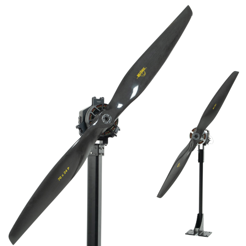
When testing a propeller to characterize its thrust, torque and efficiency, you might be wondering how to install the propeller. The image below shows how we recommend you test your propeller:

The theory behind this setup, which was experimentally verified, is that the airflow upstream of the propeller is slower than the airflow downstream. The airflow around the propeller has a cone shape. The area of the air affected upstream of the propeller is larger and, due to the conservation of mass, it is also slower. Since drag losses are proportional to the square of the velocity, an obstacle upstream will has a smaller effect on the thrust than an obstacle downstream.
The air moving slower causes less drag losses due to the testing equipment, which is why we recommend testing in the configuration of the image above. Testing with the thrust in the other direction can create a 3-20% difference in your results due to the airflow interaction with the fixture.
In the configuration presented in the image above, the thrust will be positive by default. You can always reverse the reading by activating the reverse thrust checkbox of our software in the ”Utilities” tab if you prefer not to have to do that operation in your spreadsheet editor after.
Note that your quadcopter arm or airframe will also have an impact on the thrust in flight. When testing in a wind tunnel, you also have to run a test with the propeller removed from the test fixture to characterize the drag of the measuring instrument, which you will subtract from your test results.
Further reading:
Theys, Bart & Dimitriadis, G & Hendrick, P & De Schutter, J. (2016). Influence of propeller configuration on propulsion system efficiency of multi-rotor Unmanned Aerial Vehicles. 195-201. 10.1109/ICUAS.2016.7502520.


 Back to Blog


Leave a comment