 Back to Blog
1. Applicable products
- RCbenchmark Series 1780 Thrust Stand
2. What describes your problem?
Please find within the following table which describes your problem. Once selected, mark down the troubleshooting points to follow.
If you are planning to run dual-motor testing, we recommend starting to read the whole document from section 3.1.

3. Problem specific troubleshooting
3.1 What is back-to-back and face-to-face testing and which configuration shall I choose to test?
In a dual-motor testing environment, you may have two motors and propellers to be mounted on a propulsion system in order to increase the output thrust and neutralize the torque without adding much extra structure on the drone.
In the Series 1780 Thrust Stand and Dynamometer, the following versions may allow you to run coaxial tests:
- 75 kgf - 500 A: allows back-to-back coaxial, face-to-face coaxial and offset testing

The nature of the dual-motor testing introduce some new parameters:
- Axial distance: shown as Z in the figure above, physical offset between two propellers in the axial direction
- Radial offset: shown as e in the figure above, physical offset between two propellers in the radial direction
- Diameter difference: two propellers may have different diameters
- Pitch difference: two propellers may have different pitches
There are also a few extra parameters when it comes to controlling two motors and ESCs: the rotation speed difference between two propellers and the air speed and pressure generated by the propeller in the front. It is complicated to model all these parameters in a single test and we suggest to first find out the target setup you may need to start a test.
Generally speaking, most of the coaxial propulsion systems on a UAV use the back-to-back design. The advantage of a back-to-back design is mainly that both motors are mounted onto the same drone frame structure and may potentially reduce the material and weight on the drone structure.
If you wish to use the Series 1780 Dynamometer to run back-to-back tests, please keep in mind that there is a minimum coaxial distance imposed on the thrust stand. You may not be able to reach the desired distance between your two propellers due to the distance restriction. See section 3.2 for more details about the coaxial distance that you may reach.
When a distance cannot be reached in a back-to-back setup, we recommend using the face-to-face setup as an alternative. Face-to-face setup allows you to reach a minimum distance of 0 in theory. The disadvantage of this setup is that the aerodynamic effect may not be exactly the same as a back-to-back setup.
From what RCbenchmark has tested internally, we found out that the difference between a back-to-back setup and a face-to-face setup is not significant when all propellers are large enough. The smaller the propellers are, the smaller the thrust they may generate and thus make the drag effect more obvious and the test result less accurate. When your propellers are larger than 32” on the 25 kgf and 40 kgf version thrust stand, and larger than 40” on the 75 kgf version thrust stand, you may convert the thrust stand into a face-to-face setup to run the coaxial tests in order to a lower coaxial distance.
3.2 What is the coaxial distance and how shall I define this value?
As stated in section 3.1, the coaxial distance, defined as Z, is the physical distance between two propellers on the axial direction. This parameter is significant to the dual-motor testing because it determines the airflow inlet from the upstream propeller towards the downstream propeller.
When doing coaxial testing, it is extremely important to have two motors counter-rotating. This means one propeller in clockwise direction (CW) and another in counterclockwise direction (CCW). They must generate either push or pull (thrust) in the same direction, while attempting to neutralize the torque.
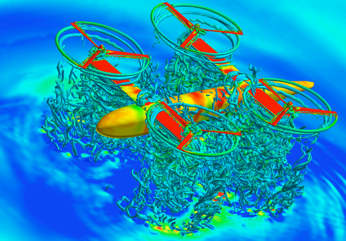
Figure copyright: NASA@SC15
When it comes to airflow, the upstream propeller will generate air flowing through both axial and radial directions as you may see in the figure above. This will require the downstream propeller being able to attack the incoming airflow in both directions.
The smaller the Z is, the closer those two propellers become. After the acceleration and twisting, air flows out from the upstream propeller with axial and radial speed and pressure and the closer the downstream propeller is placed, the more turbulence and more severe radial resistance it must suffer.
In coaxial testing, we use the term Z/D factor to represent the relationship between the axial distance Z between two propellers and the propeller's diameter D. If you have two propellers in different sizes, use the smaller one. The Z/D factor is a significant factor to be controlled and observed in coaxial testing and we suggest this factor shall not be smaller than 0.15.
The smaller the Z/D factor is, the more easily the downstream propeller being affected by the turbulence. You may observe negative thrust or torque and other phenomena related to the low Z/D factor.
To start the test, we suggest to first try testing in a face-to-face setup and reach the minimum Z/D factor of 0.15. Gradually increase this factor and make measurements until you can reach the best efficiency, mark down the Z distance and see if you may reach it with the back-to-back coaxial:
- Series 1780 25 kgf & 40 kgf versions: 95 mm + 2 x motor’s height
- Series 1780 75 kgf version: 280 mm + 2 x motor’s height
It’s hard to predict the overall performance of a coaxial system without testing realistically different Z/D factors. Please also keep in mind that when two propellers have different diameters and pitches, the optimum Z/D value may also differ.
In a common application, some theories indicate that we shall have the downstream propeller larger in diameter and higher in pitch: it can theoretically avoid the downstream propeller under full turbulence and an increased attack angle can also help to tackle the counter-rotating air flow. You may see some of our tests on the RCbenchmark database:
https://database.tytorobotics.com/tests
3.3 What is the radial offset distance and how to manipulate this value?
Radial offset distance, shown as e in the figure located in section 3.1, is the offset of two central axes in any radial direction. In most of the dual-motor or coaxial propulsion systems used on drones, designers tend to keep both motors on the same axis thus a zero radial offset.
Generally speaking, we use the term “overlapping percentage” to characterize potential aerodynamic effects of the airflow impact on the downstream propeller. When two propellers are at the same size and without any radial offset, we can say the overlapping percentage to be 100%. The smaller the overlapping percentage becomes, the smaller turbulence the downstream propeller may suffer and can potentially increase the thrust generated.
The advantage of radial offset is a decreased overlapping percentage in order to avoid direct turbulence effect towards the downstream propeller. This may potentially increase the thrust the downstream propeller can generate.
There are multiple constraints for a radial offset or a smaller overlapping percentage. One of the major disadvantages of radial offset is mainly about the complexity when designing the flight control system. The extra motor and propeller in a different position may increase significantly the complexity of the flight control design as each motor may be regarded as independent. Drone’s frame and position restrictions can also impose obstacles for a larger radial offset.
On the thrust stand Series 1780, you may be able to adjust the radial offset with certain setups. Please keep in mind that the diameter difference between two propellers, and the axial offset distance may also affect the optimum thrust. See section 3.4 to learn more about how to start a coaxial design and testing.
3.4 To put everything together: how to start coaxial tests?
As we have introduced different parameters in the previous sections, we will then focus on how to put everything together and to start planning dual-motor propulsion system design.
First, to summarize all the factors that we have mentioned earlier:
- Upstream propeller: diameter and pitch
- Downstream propeller: diameter and pitch
- Z/D factor: axial distance divided by the upstream propeller’s diameter
- Overlapping percentage: surface area of two propeller overlapping
To start a design:
- Determine the motor layout: back-to-back or face-to-face on your drone.
- Make a target thrust output that you wish to reach for the total system.
- Assuming that you will use the same motor and propeller on the propulsion system, then there can be a 25% to 35% thrust loss in the downstream propeller. Calculate the individual thrust output required.
- Select a few motors and propellers that may achieve the required thrust while respecting the dimension restrictions on your drone: use the thrust stand to run single-motor tests in order to first characterize the general performance of your chosen motors and propellers.
- Try to pick multiple propellers that can adapt on the same motor and test those: for example, you may adapt a 26”x8.5” and 28”x9” and 30”x10” propellers on the same motor, make extra tests with all the possible combinations.
- In a back-to-back design, measure the height of your motors and the minimum thickness of the mounting frames in order to calculate the minimum Z (axial distance) that you may achieve.
- Place the smallest propeller possible (that can generate adequate thrust and with good efficiency tested in a single-motor) as the upstream propeller and use the same one for downstream.
- Derive the Z/D factor and see what is the minimum to be achieved, mark down the number and design a few groups of tests with an increment. For example, when you find out the minimum Z/D to be 0.17, you may try to test the stand in 0.17, 0.20, 0.23, 0.26, etc. We regard over 0.5 as over-distanced and it makes no sense to approach or exceed that.
- Generally speaking, the bigger the Z is, the better it becomes for the downstream propeller. But due to the material thickness and drone frame limitations, the bigger the Z is the heavier the drone will become. Try to find the distance that compromises for a better efficiency and overall thickness.
- Test coaxial face-to-face or back-to-back for the target distance and run full power: see if the dual-motor system can generate enough thrust for take-off. Test further to obtain the individual performance of each motor and propeller in the dual-motor setup: efficiency, power consumption and calculate flight time.
- Try to run the previous step with a higher pitch propeller in the downstream position: see if the individual efficiency gets improved;
- If you wish to achieve a better efficiency, you may first try to increase diameter and pitch of the downstream propeller; and then to increase Z distance; for most of the applications, the least ideal approach is to add radial offset as it is complicated and extremely hard to predict the overall optimization in performance.
3.5 Can I use the Series 1580/1585 for coaxial testing?
Unfortunately, the Series 1580/1585 does not support dual-motor control and testing. If you wish to test dual-motor, we suggest using the Series 1780.
The Series 1580/1585 can only be communicating with ONE computer at a time, the software cannot support multiple opening sessions.
If you must test two motors on the Series 1580/1585, you may then:
- Have 2 computers and one for each thrust stand Series 1580/1585
- Open the software on each computer and make measurements on each PC
- Use one circuit to control: plug ESC A to the ESC port on circuit A, and plus ESC B to the Servo port on circuit A.
- Make sure that you start data logging simultaneously on both stands when you start the test
When you have propellers larger than 18”, we suggest using the Series 1780 for your coaxial testing.
4. Problems persist?
If you still cannot solve your problem, email us at sales@tytorobotics.com. We support all issues related to the measurement tools itself, and we can provide limited support regarding your test setup and power-train selection. You may go to our online database to obtain more information: