
 Back to Blog
1. Applicable products
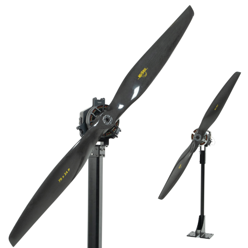
- Series 1520 Thrust Stand
- Series 1580 Test Stand
- Series 1585 Test Stand
2. What describes your problem?
Please find within the following table which describes your problem. Once selected, mark down the troubleshooting points to follow.

3. Problem specific troubleshooting
3.1 The load cell seems damaged: cracks, fragments, ripped silicone.
The load cells are the key components on the Series 1520, 1580 and 1585. If you observe any physical damage on the load cells, please follow this guideline.
- Disconnect the thrust stand from the power source.
- When voltage drops below 15 V, approach the stand and visually inspect the load cells. For the Series 1520, there is only one force load cell to inspect; for the Series 1580/1585, you will need to inspect all three load cells.
- If necessary, unmount the load cells from the stand to further inspect.
- If you find an obvious crack or the load cell was broken into fragments, please take a picture of the broken section in a close view:
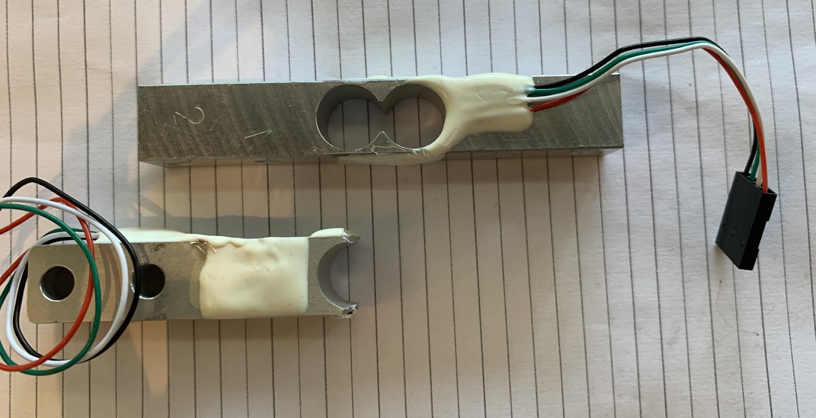
- If the load cell’s silicone is ripped off, please also take a picture of the damage area and see if the strain gauges were exposed. If the damage is only on the silicone, the load cell may still work normally.
- Please send the picture to support@tytorobotics.com and include the following info:
- Subject: S1580 Load cell damage
- The picture of the damaged area
- Your purchase invoice number or shipment record
- Your shipping address
- If your product is still under warranty and used within specifications, we will ship you a replacement load cells. Cases where the load cell was overloaded, or loaded in unusual configuration with a high offset load are not covered under warranty. An example of a high offset load is when the motor is mounted with an offset relative to the default position on the motor plate, which creates an additional torque on the load cell.
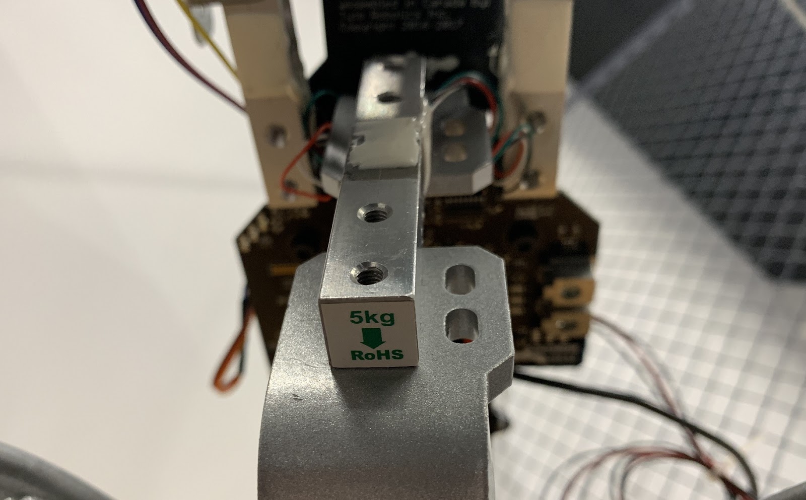
- If your product is unfortunately out of warranty, we invite you to visit our online store to purchase replacement load cells: The Series 1520 requires 1 x 5 kgf load cell for the thrust; the Series 1580/1585 requires 1 x 5 kgf load cell for the thrust and 2 x 2 kgf load cells for the torque.
3.2 I have a broken connector on my load cells.
Please confirm if the broken connector is on the load cells or on the circuit. If you may have a broken connector on the circuit that allows the load cells to be plugged in, please refer to section 4.1: cross-reference to other types of problem.
- Disconnect the thrust stand from the power source.
- When voltage drops below 15 V, approach the stand and visually inspect the load cells. For the Series 1520, there is only one force load cell to inspect; for the Series 1580/1585, you will need to inspect all three load cells.
- Unplug the connector carefully from the circuit.
- Inspect if the black crimped connector: check the broken area and if the four-color cables can still connect to the male connectors.
- If not, you will need to purchase the replacement load cells. We may invite you to visit our online store to purchase replacement load cells: The Series 1520 requires 1 x 5 kgf load cell for the thrust; the Series 1580/1585 requires 1 x 5 kgf load cell for the thrust and 2 x 2 kgf load cells for the torque.
3.3 My calibration did not pass.
This section is only applicable to Series 1580/1585. The calibration process differs on the version of the circuit as well as the software that you may be using. Please follow this guideline if the system keeps indicating that the calibration does not pass after multiple attempts.
- Go to RCbenchmark’s website and download the most up-to-date software: https://www.tytorobotics.com/blogs/manuals-and-datasheets/rcbenchmark-software-overview
- Install the software and open the GUI.
- Please make sure that:
- You are using the original load cells *(2 x 2 kgf & 1 x 5 kgf) for your Series 1580/1585
- You are not using any unlock code
- You are using the Series 1580 hinge or Series 1580/1585 L-bracket to connect the load cells to the motor mount.
- Check that the 5 kgf load cell is being used on the thrust section. Make sure it is connected to the central connector on the circuit indicating “Thrust”.
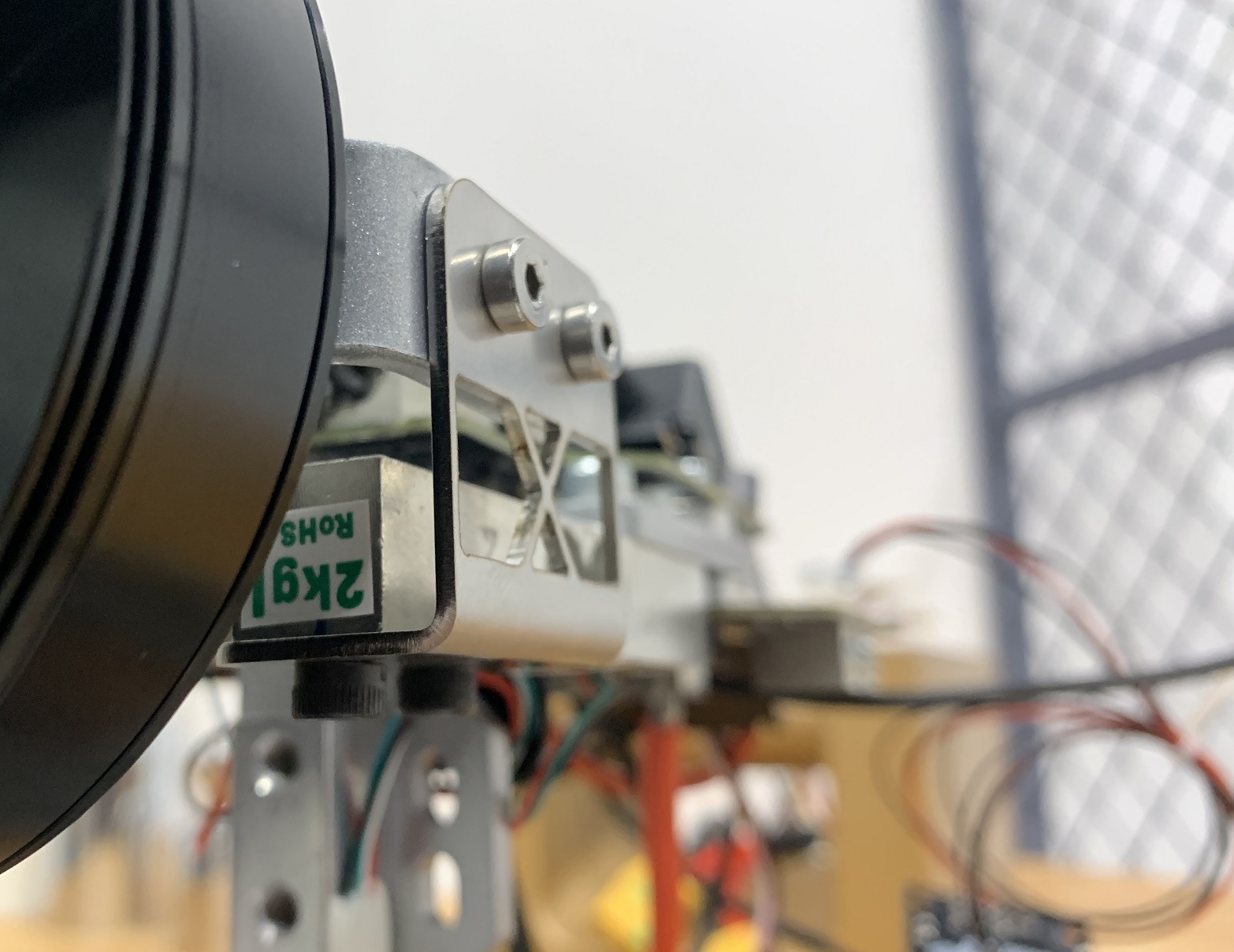
- Check that the two 2 kgf load cells are on the torque section. Make sure they are connected on the left & right connector on the circuit indicated by “L” and “R”.
- Connect the Series 1580/1585 to the GUI and check if the calibration warning is active:

- Now go to the Utility tab and try to do the thrust calibration wizard again.
- Before placing the stand vertical, please first make sure that all fasteners are properly tightened.
- You may keep your motor on the motor mount as long as there is enough space to place the 200 g weight on the mount and not interfere with the propeller.

- When placing the weight, please make sure that you do not touch any part of the thrust stand other than the motor mount. If your motor and propeller are still on the stand, please make sure the propeller stays at where it was before and during the calibration. Small movements and rotations of the propeller can affect the calibration result and make it fail.
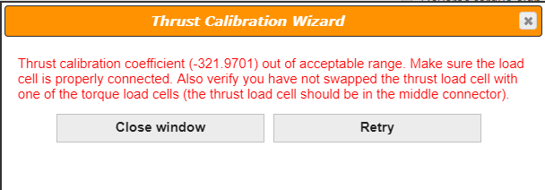
- If the calibration still shows that the coefficients are still out of the acceptable range, please make a screenshot as such:
- Now, move on to the torque calibration and make sure that the calibration bar is perfectly horizontal. You may check it with a bubble level or a spirit level.
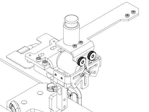
- Make sure the 200 g weight is properly tangent to the two screws:

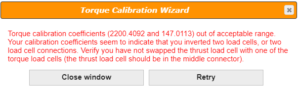
- If the torque calibration still shows that the coefficients are unacceptable, please make a screenshot as such:
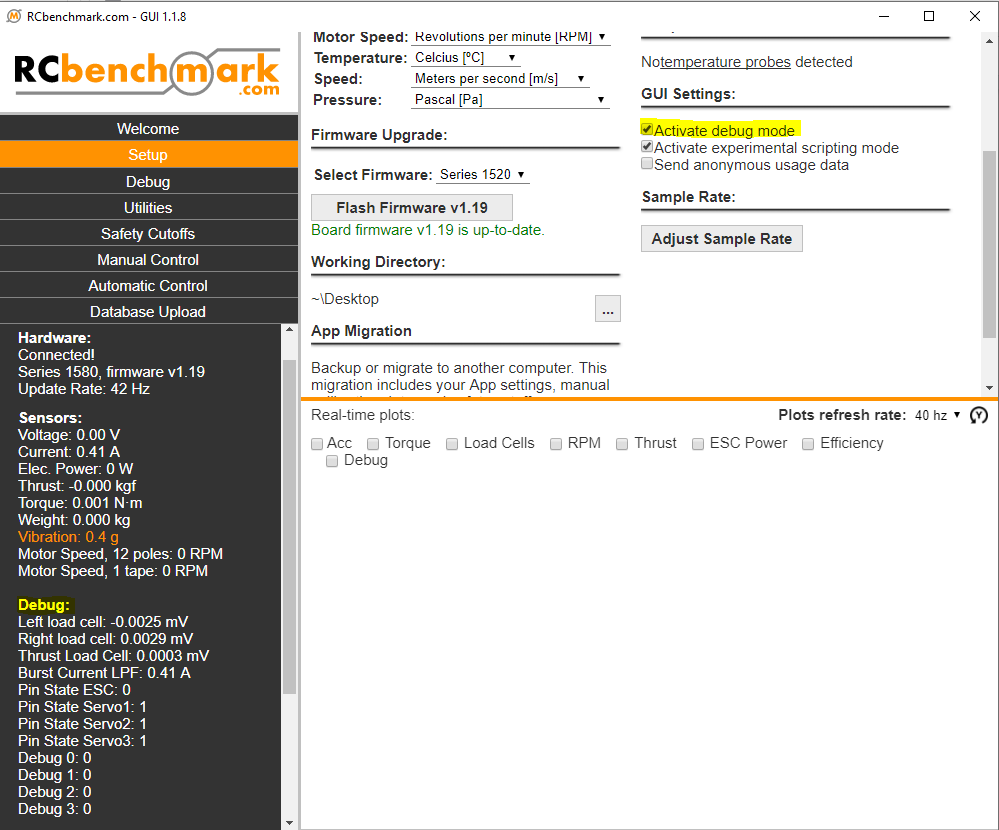
- Please then go to the Setup tab and check the box “Activate debug mode”. Once selected, you will be able to see the load cell raw values on the bottom-left:
- Try to manually apply force and torque to the thrust stand and see if these raw values change. If not, please refer to section 3.2 to inspect if the connection is intact.
- If all the values do change when you manually apply the loads, please remove the load and make a screenshot of those raw values when there is no external force and torque applied to the stand.
- Please send your request to support@tytorobotics.com and include the following info:
- Subject: S15 Calibration and load cell
- Let us know if the thrust calibration or the torque calibration NOT pass
- Screenshot of the last page of thrust calibration wizard, or the last page of torque calibration wizard, or both
- Screenshot of the load cell raw values
- Pictures of the load cells physically mounted on the stand
- Pictures of the circuit with the three 4-pin connectors that connect the load cells to the circuit
- In case there is a load cell failure, please then refer to section 3.1 to consult the procedure for a replacement.
3.4 I think I have the wrong thrust / torque reading.
The load cell measurement should measure forces with the accuracy specified in the datasheet. If you find that the thrust and torque measured are lower than what the motor and propeller manufacturer advertised, please refer to section 4.1. You can check the accuracy of the tool with the following procedure:
- Please place the stand vertically and connect the stand to the GUI.
- On the bottom-left corner, click “Tare the load cells”

- Once tared, place the 200 g on the motor mount and read the thrust value:

- If the value reads 200 +/ 5 g, the reading is still regarded as accurate. You may try to use a 1 kgf standard weight to check the static thrust value.
- Mount the calibration bar back on the Series 1580/1585 and then place the 200 g weight on the first position, then click Tare:
- Once tared, move the weight to the 2nd position and check the value:
- If the measured torque reads 0.256 +/- 0.02 Nm, the torque reading is still regarded as accurate.
- If the thrust or torque value is out of the acceptable range indicated above, your load cell can potentially be damaged. Please refer to section 3.1 to troubleshoot and to consult the procedure for the replacement.
- If your measured values are within the range but you still have doubt about the measurement, we recommend a new calibration to the system. Please note that the rotating motor and propeller can generate dynamic errors due to the air drag, vibration, etc. We recommend reading the guideline SITMDG to know about the limits and constraints using our tools.
4. Problems persist?
We support all issues related to the measurement tools itself, and we can provide limited support regarding your test setup and power-train selection. If you need extended support for your specific tests, manufacturing facility or UAV, contact us at sales@tytorobotics.com. We offer extended support contracts including phone and video conference at affordable rates.
To obtain a solution to your problem faster, please indicate which troubleshooting steps you have already done. Also, include the debug log from the software. If relevant, please also include screenshot or pictures of the issue.
4.1 Cross-reference to other types of problem
- S15CIR: broken connector on the circuit that connects to the load cell
- SITMDG: the thrust and torque discrepancies can be dynamic error or the motor / propeller manufacturers overstate their performance
4.2 Cross-reference from other types of problem
- SITMDG: when having >100% efficiency, it can be a wrong value on the torque